Authors
Raquel G. Hernandez, DO and Denise Joffe, MD
Seattle Children’s Hospital
Objectives:
Describe the detailed anatomy of the mitral valve (MV) using two-dimensional (2D) transesophageal echocardiography (TEE) based on the American Society of Echocardiography/Society of Cardiovascular Anesthesiology Guidelines.
This document will review the comprehensive 2D examination of the MV. Three-dimensional (3D) echocardiography will be used to help illustrate the anatomy and facilitate an understanding of 2D views where applicable. This tutorial consists of two sections; part 1 will discuss the comprehensive TEE exam of the MV and part 2 will detail MV pathology.
Normal Anatomy of the MV
The anatomical components of the MV include the annulus, leaflets, chords and papillary muscles. Normal function of the MV depends on the integration of these structures and on the absence of supravalvar pathology or significant disease of the left ventricle (LV) such as a hypoplastic ventricle or severe LV dysfunction.1
MV disease may cause abnormalities in LV size and function, pulmonary venous flow, left atrial (LA) size, pulmonary artery pressure, right ventricle (RV) size and function, and tricuspid valve function. A complete exam of the MV includes echocardiographic imaging of those structures in addition to an examination of the MV apparatus.
- Annulus
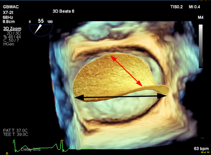
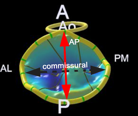
The annulus is a fibrofatty non-planar ring with a geometric shape similar to a riding saddle (or chip), with two axes, the anteroposterior (AP) axis and an orthogonal axis along the commissure (Figure 1a-c). The AP dimension is usually in a higher plane and is measured in a mid-esophageal aortic valve long-axis (ME AV LAX) view whereas the commissural diameter should be measured in the mid-esophageal bi-commissural (ME bi-com) view. The normal annular shape in adults yields a shorter AP diameter than commissural diameter, and studies in children suggest the shape does not vary significantly with patient age. However, diseased states usually result in a more planar (flatter) and more circular valve.2
Figure 1 A-D
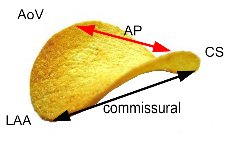
A. A chip is used to demonstrate the shape of the normal non-planar MV. The AP diameter is the upper border of the annular plane (red arrow). The normal valve has a longer commissural diameter than AP diameter (black arrow compared to red arrow.
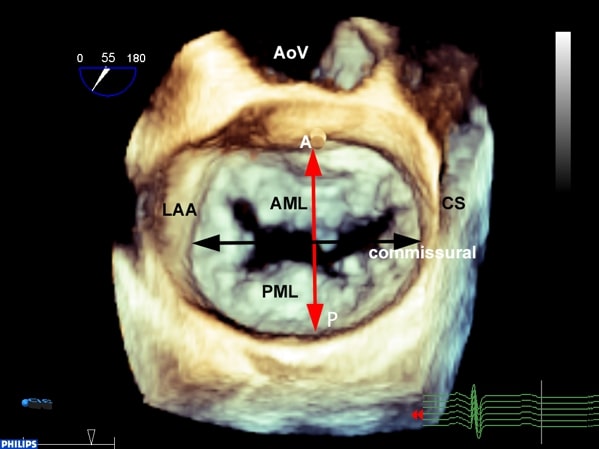
B. A three-dimensional (3D) TEE en face view of the MV. The non-planar shape of the valve is not appreciated in a 3D image unless a model is created using 3D software.
C. The chip is overlaid over the mitral annulus in order to appreciate the shape of the MV.
D. Model of MV created using a 3D image. The non-planar shape is better seen compared to the 3D image.
A anterior, P posterior, Ao aorta, AL anterolateral, PM posteromedial, LAA left atrial appendage, AP anteroposterior, CS coronary sinus, AML anterior mitral leaflet, PML posterior mitral leaflet
- Leaflets
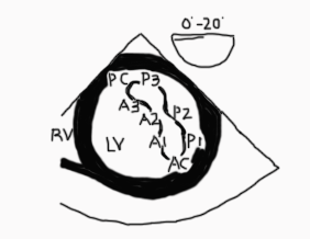
The MV has an anterior and a posterior leaflet. The circumference of attachment of the posterior leaflet to the annulus is greater than the anterior leaflet. The most common numbering of the leaflets is based on the adult nomenclature from the Carpentier classification.3 The posterior leaflet has indentations called scallops and are numbered from anterolateral to posteromedial into P1, P2, P3 segments. The anterior leaflet may not have readily identifiable scallops. The corresponding area of the anterior leaflet that coapts with the posterior leaflet is numbered according to the posterior leaflet-A1, A2, A3. Scallops on the posterior leaflet are even less well developed in children. If a scallop extends deep into the annulus, then it is called a ‘cleft’ which is different from a cleft that is seen in an atrioventricular canal defect (see part 2). The leaflet edges meet at two commissures named the anterolateral and posteromedial commissure (Figure 2).3
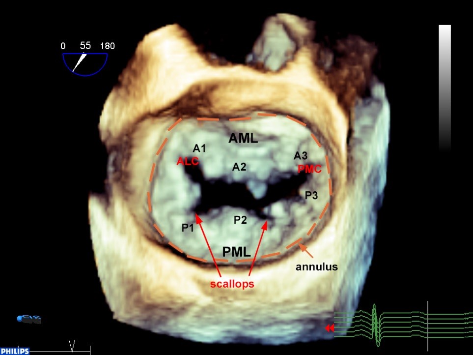
Figure 2. 3D en face TEE image of the MV. P1-P3 designates the segments of the posterior leaflet roughly divided by the scallops. The anterior leaflet numbers (A1-3) mirror those of the posterior leaflet. The annulus is outlined in orange.
AML anterior mitral leaflet, PM posterior mitral leaflet, ALC anterolateral commissure, PMC posteromedial commissure
- Papillary muscles, chordae, and left ventricle
The anterolateral (ALPM) and posteromedial (PMPM) papillary muscles support the mitral leaflets via the chordae tendinae. They run parallel with the long axis of the LV and are aligned with the commissures (Figure 3). Primary chords attach to the free edges of the leaflets, and secondary chords to the undersurface of the leaflets.3 The ALPM sends chords to both the anterior and posterior portions of A1 and P1 and the lateral part of A2, P2. The PMPM sends chords to both A3 and P3 and the medial part of A2, P2. The middle of the valve is free of chords3 (Figure 4 A and B).
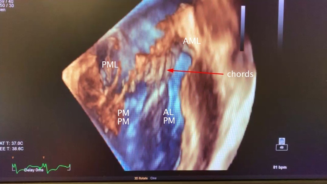
Figure 3. 3D TEE transgastric long-axis image of the LV rotated around the z axis demonstrating normal MV subvalvular anatomy. The MV apparatus consists of the LV, papillary muscles, chords and leaflets. See text for full description.
ALPM anterolateral papillary muscle, PMPM posteromedial papillary muscle, AML anterior mitral leaflet, PML posterior mitral leaflet

Figure 4A 3D TEE en-face view of the MV. If the posterior annulus is cut along the line indicated by the scissors and hatched red line and filleted open, it would result in panel B.
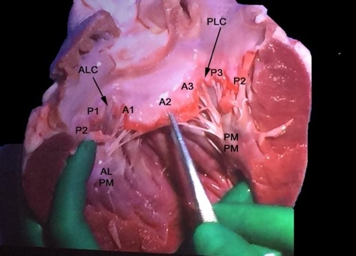
Figure 4B In this specimen of the LV the entire anterior leaflet is flanked by the lateral (P1 and lateral part of P2) and the medial (P3 and the medial part of P2) posterior leaflet. Note that the ALPM sends chords to lateral portions of the anterior and posterior leaflet and the PMPM sends chords to the medial portions of the anterior and posterior leaflets. There are no chords in the middle of the leaflet (middle of A2 or P2).
ALC anterolateral commissure, PMC-posteromedial commissure, ALPM anterolateral papillary muscle, PMPM posteromedial papillary muscle
Comprehensive TEE evaluation
Pre-operative and intra-operative echocardiographic evaluation
Preoperatively, the MV apparatus should be examined using 2D and in some cases 3D transthoracic echocardiographic (TTE) modalities. There are times when the improved resolution of TEE is necessary to fully appreciate the mechanism of disease and can assist operatively planning. Intraoperatively, TEE is the imaging modality of choice. 3D probes are available for older children, usually weighing 25 kg or more, although smaller pediatric 3D TEE probes are in development. 3D imaging is able to provide anatomical details that can help localize leaflet pathology. Each component of the MV should be examined in multiple planes with and without color flow Doppler (CFD). The remainder of both tutorials will describe imaging with 2D TEE only.
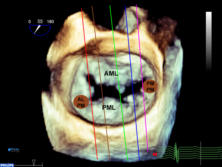
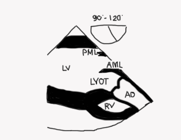
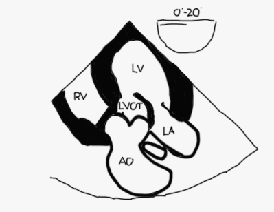
It is important to avoid relying solely on the omniplane (multiplane) angle when imaging structures because of variability in cardiac anatomy and abnormal cardiac rotation in some patients especially those with congenital heart disease. Figure 5 demonstrates standard imaging planes and the usual starting angles at which they’re obtained.
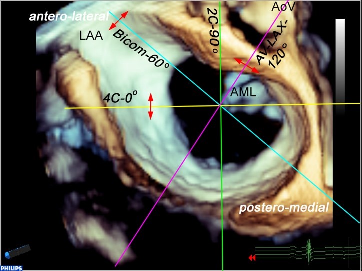
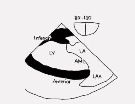
Figure 5. 3D TEE image of an open MV in diastole. The lines indicate the orientation of 2D imaging planes that are used to evaluate the valve. The double red arrows are meant to indicate that as the plane is moved in the direction of the arrowhead, a different part of the MV is visualized. For example, in the four-chamber view, the image will look the same as the probe images either the anterolateral (anterior flexion and slight withdrawal of the probe) or posteromedial part of the valve (insertion and retroflexion of the probe). In a bi-com view, if the probe is turned to the left (counterclockwise), the posterior leaflet is imaged, whereas turning it towards the right (clockwise) images the anterior leaflet. In the aortic valve long-axis view, a leftward rotation (counterclockwise) images the anterolateral portion of the valve and a rightward rotation (clockwise) images the posteromedial part of the valve.
LAA left atrial appendage, AML anterior mitral leaflet, AoV aortic valve, 4C four chamber, Bicom bicommissural, 2C two chamber, AV-LAX aortic valve long-axis view
Technical aspects of performing measurements are more standardized in adults than in children. For example, mitral annular measurements are made at end systole in adults whereas they are made in diastole in children. Further, annular measurements in pediatric patients are often made using off-axis planes such as the four-chamber view. Measurements are compared to normative data and given a Z-score. Scores above +3 or below -3 are usually in the severely abnormal range.
2D TEE Examination
A comprehensive 2D TEE examination of the MV consists of nine cross sectional views. The valve is examined by 2D imaging and with CFD and spectral Doppler, with a more detailed exam dictated by pathology. See table 1 for guidelines on how to examine each structure. In the following sequence, the exam begins in the esophagus in a mid-esophageal four chamber view with the MV centered in the image. The probe angle is rotated to examine to valve. The probe is then advanced into the stomach to obtain additional views.
Mid esophageal four-chamber view (ME 4C; Figure 6 and Video 1)
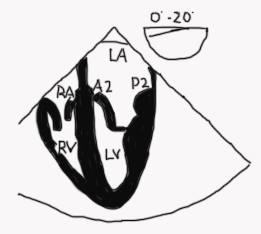
Figure 6
- The anterior leaflet (usually A2) is on the left and the posterior leaflet (usually P2) is on the right of the image, however depending on the position of the probe you may see more of A1/P1 or A3/P3 in a ME 4C view. Use landmarks that come into view such as the aorta and coronary sinus to help determine the location of the probe
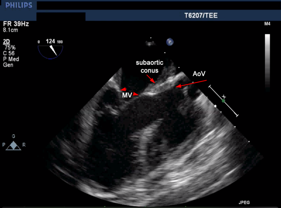
- The anterior leaflet is in continuity with the aortic valve (unless there is transposition of the great arteries or a subaortic conus- see Figure 11)
- To visualize the left ventricular outflow tract (LVOT) withdraw or anteflex the probe to a modified 5 chamber view. In this view, the anterolateral part of the leaflets and the anterolateral commissure (A1/P1) are seen.
- Advancing or retroflexing the probe sweeps the image plane towards the posteromedial part of the valve (A3-P3) and posteromedial commissure.
- CFD evaluation of MV (for regurgitation or stenosis) and pulmonary veins
- Spectral Doppler alignment of MV inflow is optimal
- Left atrial appendage evaluation
- Subvalvular apparatus and papillary muscle evaluation
- RV evaluation
Video 1
Legend: RA right atrium, RV right ventricle, LA left atrium, LV left ventricle, A2 middle segment anterior mitral leaflet, P2 middle segment posterior mitral leaflet
Mid esophageal two-chamber view (ME 2C; Figure 7 and Video 2)
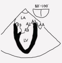
Figure 7
- The entire anterior leaflet is on the right of the image in addition to left atrial appendage. The posterior leaflet and coronary sinus are on the left of the image. The posteromedial papillary muscle and commissure are visible
- Subvalvular apparatus and papillary muscle evaluation
- CFD evaluation of MV for regurgitation/stenosis
- Left atrial appendage evaluation
Video 2
Legend: LA left atrium, LV left ventricle, P3 posterior or medial segment of posterior mitral leaflet, A3 posterior or medial segment anterior mitral leaflet, A2 middle segment anterior mitral leaflet, A1 anterior or lateral segment mitral leaflet
Mid esophageal mitral commissural view (ME bi-com; Figures 8-9 and Video 3)
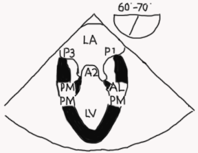
Figure 8
- One of the most important and informative views since the location of disease along the coaptation line can be identified
- MV appears trileaflet with P1 on the right, A2 in the center, and P3 on the left. It can be a confusing view to figure out because it appears as though the A2 leaflet is coapting with P1 and P3. However, that is not happening! P2 is posterior to the imaging plane and it is coapting with A2 (see Figure 9 A-C).
- Both papillary muscles should be visible in a true commissural image
- Subvalvular apparatus and papillary muscle evaluation
- CFD evaluation of MV
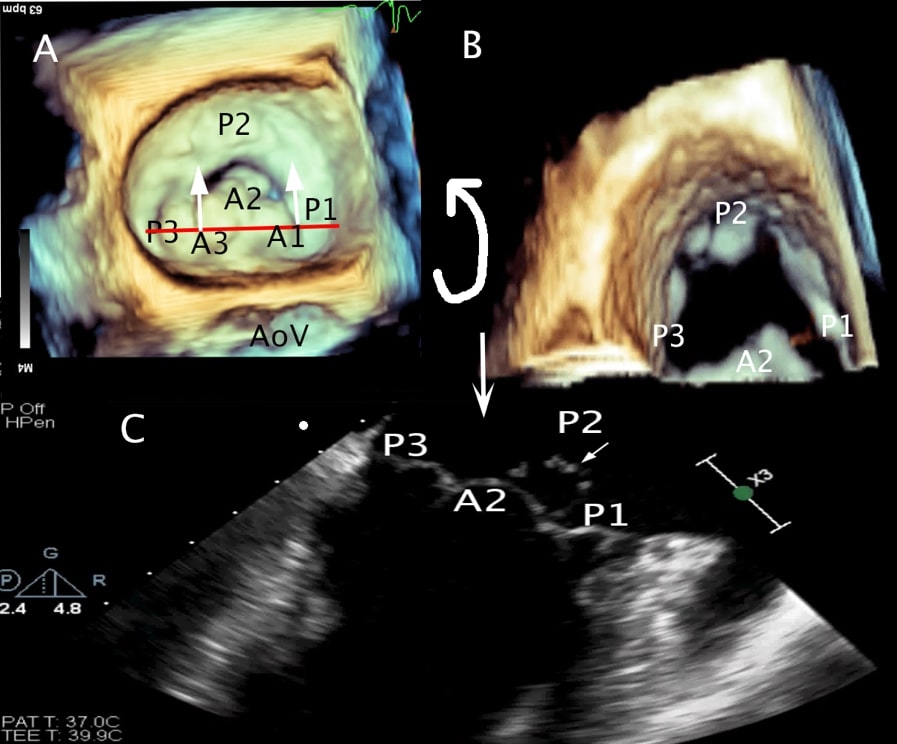
Figure 9A to C. A 3D TEE en face view of the MV with a red line demarcating the cropping plane of a bicom view. The white arrows indicate the direction of cropping (towards the posterior aspect of the valve). B 3D TEE en face view of the MV with the cropping plane advanced. If the image is rotated up, the result is the 2D bicom view with P3 on the left, A2 in the middle and P1 on the right of the screen as shown in panel C. In this image there is a P2 prolapse. P2 is seen behind A2 because it is prolapsing above the annulus.
Video 3
Legend: LA left atrium, LV left ventricle, P3 posterior or medial segment of posterior mitral leaflet, A2 middle segment of anterior mitral leaflet, P1 anterior or lateral segment of posterior mitral leaflet
Mid esophageal AV long axis view (ME AV LAX; Figure 10 and Video 4)
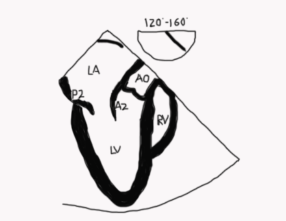
Figure 10
- Mitral and aortic valves are visualized as is aorto-mitral continuity (Figure 11)
- Orthogonal to the bicom view
- This image shows the “highest” points of a normal MV annulus. When leaflets are seen above this plane they are said to either be billowing, prolapsed or flail
- Neither papillary muscle should be seen if the A2-P2 leaflets are being imaged since there are no papillary muscles or chords in the middle of the valve
- Turning the probe to the left (counterclockwise) will scan towards the anterolateral commissure and eventually the left atrial appendage
- Turning the probe to the right (clockwise) sweeps the scan to bring A3/P3 and the posteromedial commissure and eventually the coronary sinus into view.
- It is crucial to understand that this imaging plane is perpendicular to the ME bi-com view and regardless of whether the lateral or medial part of the valve is being imaged, the ME AV LAX image will appear the same except for the absence of a papillary muscle if the middle of the valve is imaged (A2-P2). (Figures 4B, 12)
- CFD evaluation of MV for regurgitation/stenosis and pulmonary veins
- Spectral Doppler alignment of MV inflow is optimal
- Subvalvular apparatus and papillary muscle evaluation
Video 4
Legend: LA left atrium, LV left ventricle, P2 middle segment posterior mitral leaflet, A2 middle segment anterior mitral leaflet, AV aortic valve
Figures 11A and B
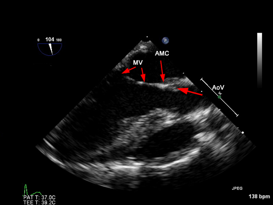
Figure 11A The normal relationship between the aortic and MV as seen in a mid-esophageal aortic valve long-axis view. There is direct continuity between the two that is referred to as aorto-mitral continuity (AMC).